Engineering, purchasing, construction & commissioning — we turn Tier-1 manufacturer technology into bankable solar, battery and flywheel projects.
“ Turning momentum into impact requires application expertise, execution discipline and long-term focus. — Eternity Renewable
Renewable-energy deployment is now a national priority — policy has moved from ambition to execution.
Policy doesn’t commission plants, manage interconnection or sustain long-term asset performance.
Technical choices must connect to offtake, bankability and operating value.
Clients are asking for more than awareness — they want applied, delivered results.
The industry needs technical depth, execution discipline and a skilled workforce.
Five feasibility lenses, applied at the start — so there is no redesign, rejection, overspend or delay later.
Every constraint is surfaced and resolved on paper first — before a single component is ordered.
Early access to advanced, future-ready innovation from China.
Designed to ST BESS guidelines and IEC standards.
Right-sized systems — no overspend, no idle capacity.
Engineering through installation and commissioning, faster.
A direct bridge between manufacturer capability and on-the-ground delivery — Tier-1 partners, integrated under one roof.








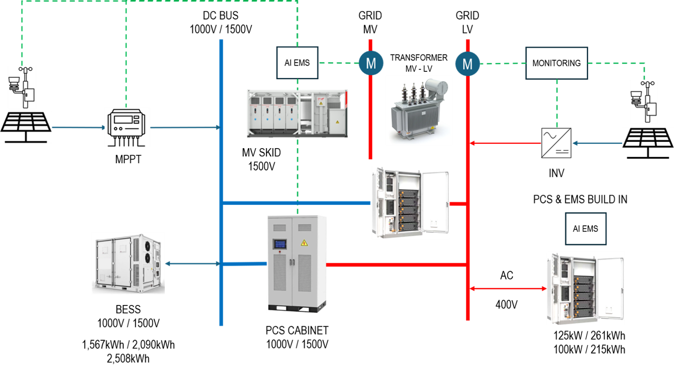
1000 V / 1500 V. Solar via MPPT, BESS and PCS cabinet share a common DC backbone.
MV skid and TBEA transformer step to grid; LV 400 V serves C&I loads and cabinet BESS.
AI EMS and a real-time monitoring layer supervise every asset and meter.
Solar makes DC, batteries store DC, the grid runs on AC. Where you convert decides losses, flexibility and return.
End-to-end round-trip efficiency, cells included.
Pays extra for rectification and a second AC step-up.
Compounds across thousands of cycles over the asset life.
| Path | DC | AC | Where AC loses |
|---|---|---|---|
| PV → Battery | 1 | 4 | PV inverter + AC→DC rectification |
| Battery → Grid | 1 | 2–3 | Separate step-up for BESS branch |
| PV → Grid | 1 | 1 | Tie — one DC→AC stage either way |
PCS-stage annual efficiency, DC vs AC, on a 288 MWp + 275 MWh plant. The gap widens as BESS-to-PV ratio grows.
Lo Franco et al., MDPI Energies, 2021
Modules vs inverter rating — modules are now the cheapest component
Of annual generation lost at the inverter limit
Of clipped energy captured by the battery
At moderate oversize ratios
Interactive curve is illustrative of a sunny day; annual figures above are from the reference model.
Power-conversion capex · RM per kWh of BESS
Around 1–3% of total system cost at 1 MWp / 1 MWh. PV modules, racking, cabling and batteries are identical in both.
A single service contract and firmware path — versus a PV inverter, battery PCS and extra transformer from up to three vendors.
DC leads by 0.5–1.5 pp on per-cycle efficiency and lower capex.
ΔNPV in favour of DC, as a share of project capex.
DC often 0.2–0.5 yr shorter. Tariff and discount rate dominate.
Greenfield C&I returns, DC vs AC. Cross-check: a modelled Massachusetts C&I case put solar + battery at 13.93% after-tax IRR and 5.5-yr payback, vs 12.18% and 5.9 yr for battery-only (pv-magazine USA, Jul 2026).
One shared inverter, fewer conversions, simplest balance of system, lowest capex.
Oversized array + DC battery recovers midday energy the export cap would trap. High if ILR ≥ 1.3
Every cycle counts; a single inverter simplifies black-start and load-following.
Free midday charging from PV plus better RTE delivers more kWh per stored kWh.
Keep the installed PV inverter; add a battery PCS on the AC bus with no extended outage.
We engineer both. Site conditions decide — DC where efficiency and clipping recovery matter, AC where you’re retrofitting or expanding in stages.
High-efficiency modules
DC-DC charge stage
Shared by PV and battery · 1000 V / 1500 V
One inverter for PV + BESS
LV 400 V or MV 11–69 kV · TBEA transformer
Dispatch, peak shaving, clipping capture · Lnxall
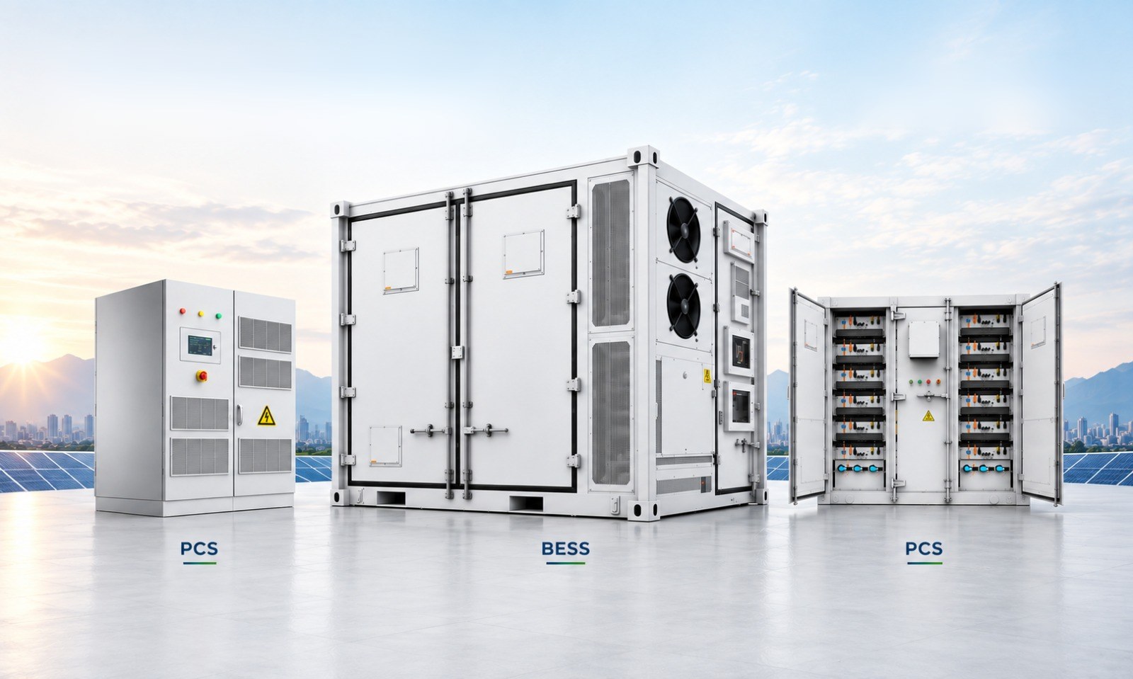
1,567 – 2,507 kWh · 1000 / 1500 V · 3,125 kWh under certification
Engineering · purchasing · construction · commissioning
Higher RTE on every cycle
Battery fills from PV on the DC bus
At 150% oversize, 1 h BESS
One vendor SLA, one firmware path
Islanding & ride-through via firmware
100 kW / 200 kWh BESS on a TNB MV time-of-use site with a 480 kW peak — constant-load setpoint vs AI dynamic dispatch.
≈ RM 8,444 per month at RM 97.06/kW peak maximum demand — from the same hardware, just better control.
Load forecast 15 min – 24 h ahead from meter history, weather and production schedule.
Receding-horizon solve to minimise the billed peak within SoC, power and degradation limits.
kW setpoint to PCS in < 5 s — commit only the next 5–15 min, then re-plan.
Compare plan with actual, recalibrate forecasts; hard safety limits always override.
1.2 MW manufacturing site · 500 kW / 1.5 MWh BESS
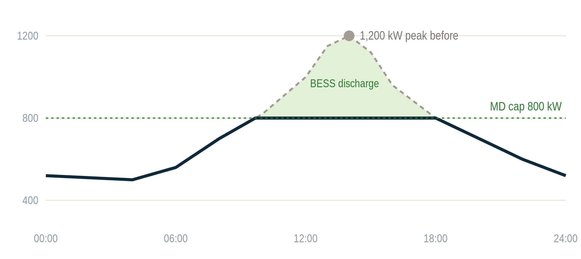
RM 54,120 / mo
RM 36,080 / mo
demand line only
before arbitrage
Rates per TNB C2 (RP4, effective 1 Jul 2025) · load profile illustrative, not a named customer.
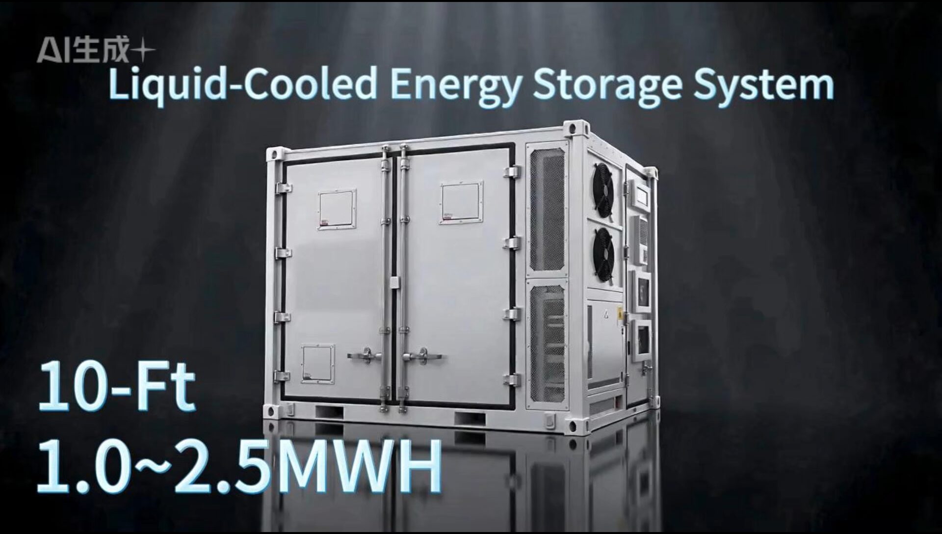
Energy-storage conversations usually focus on power and capacity. But many rigid, real-world needs sit outside the “big” logic. Our modified 10 ft container BESS is built for them — and its specs decide how well it adapts to each sector.
Urban & suburban deployments
Remote & off-grid islands
Rapid-response & mobile
Flexible large-scale layouts
These needs aren’t niche. They’re the last mile of the energy transition.
A single 10 ft enclosure, configurable as a 1000 V or 1500 V DC system across five energy capacities — paired with a separate modular PCS cabinet for LV 400 V C&I, or an MV skid for 11–69 kV output.
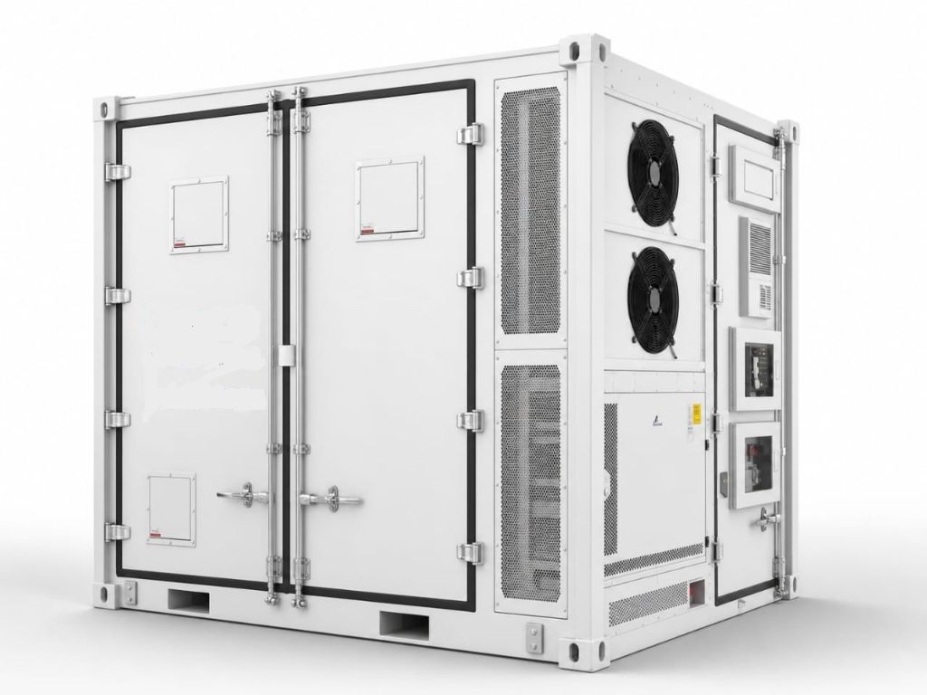
3,420 × 2,438 × 2,896 mm · 8.34 m² footprint · HQ height
Same container box — configured, not redesigned
400 V for C&I · 11–69 kV for utility
Pick a variant — every one ships in the identical 10 ft enclosure and footprint.
One cluster, one PCS, one MPPT — each battery cluster runs as an independent DC set, so the EMS controls every string on its own bus.
3.2 V · 314 Ah · 1,004.8 Wh
Series-connected cells, pack-level BMS
Series string + rack BMS sets the DC class
Clusters in parallel to the PCS cabinet
260 cells in series · 832 V nominal · 741–949 V window
416 cells in series · 1,331.2 V nominal · 1,164.8–1,497.6 V — the industry’s prevailing 1500 V cluster
| 1000 V1,567 | 1000 V2,089 | 1500 V1,671 | 1500 V2,089 | 1500 V2,507 | |
|---|---|---|---|---|---|
| Battery | |||||
| Cell | LFP · 3.2 V · 314 Ah | ||||
| Configuration | 6P260S | 8P260S | 4P416S | 5P416S | 6P416S |
| Cluster capacity | 261.2 kWh | 417.8 kWh | |||
| Total capacity | 1,567 kWh | 2,089 kWh | 1,671 kWh | 2,089 kWh | 2,507 kWh |
| Nominal voltage | 832 V | 1,331.2 V | |||
| Voltage range | 741 – 949 V | 1,164.8 – 1,497.6 V | |||
| System weight | 15.8 t | 19.0 t | TBC | 19.0 t | 22.0 t |
| Safety & environment | |||||
| Thermal | Active liquid cooling | ||||
| Safety layers | 4 · cell, pack, cluster, system | ||||
| Fire detection | Smoke, temp, gas, flood | ||||
| Suppression | Aerosol + dry-pipe sprinkler | ||||
| Protection | IP54 · C4 corrosion | ||||
| Operating temp | −20 to +50 °C · altitude 3,000 m | ||||
| Enclosure & comms | |||||
| Enclosure | Customised 10 ft HQ · 3,420 × 2,438 × 2,896 mm | ||||
| Comms | Modbus TCP · IEC 61850 · IEC 104 | ||||
Highest thermal safety and cycle life
Active liquid-cooled thermal management
Energy density of the cabinet variant
BMS protection, cell to system
| PCS cabinet | PCS1000-100X | PCS1000-125X | PCS1500-125X |
|---|---|---|---|
| Rated AC power | 100 kW | 125 kW | 125 kW |
| Rated current | 160 A | 200 A | 216 A |
| DC bus range | 680 – 900 V | 600 – 1,500 V | |
| DC bus max | 1,000 V | 1,500 V | |
| AC output | 400 / 230 V ±15% · 3-phase 4-wire · 50 Hz | ||
| Power quality | PF −1 to 1 · voltage THD < 2% · current THD < 3% | ||
| Environment | IP54 · −30 to +60 °C · 4,000 m · forced air | ||
A spare module carries load if one drops out.
Hot-swap modules cut repair time.
Idle modules shed at low dispatch.
1000 V or 1500 V · 1,567 – 2,507 kWh · 3,125 kWh in certification
Modular · DC → AC · common to both paths
No step-up transformer — ties into existing site switchgear
Transformer, MV switchgear, protection relays, aux supply
Connects at 400 V behind the meter. Peak shaving, backup and self-consumption.
Add containers in steps, still on LV — until feeder current and switchboard capacity bind.
Many containers share one MV skid and one grid tie, stepped up to 11–69 kV.
Five capacity slices · 1,567 · 1,671 · 2,089 · 2,507 · 3,125*
Behind the meter at C&I sites, or repeated into utility blocks where modular C-rate and small block granularity matter more than per-box capacity.
Single capacity · one box, one shipping SKU
Larger single-box payload for sites where transport, lifting and foundations can accept a 20 ft class and granularity isn’t needed.
Densities in kWh/m² use external footprint (modified 10 ft: 3,420 × 2,438 mm); vendor figures including service clearance will differ. C-rate, RTE, weight and IP rating of the 20 ft reference are not compared.
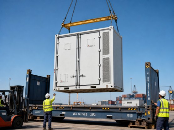
VGM covers the full configuration · tons
Six MOT conditions · media statement, 12 March 2026
> 10,000 mm total row length
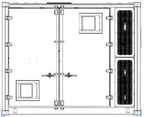
3,420 mm · ≈ 66% shorter installation row
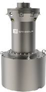
A physical storage technology: a high-speed rotor spins in a vacuum chamber under magnetic levitation, paired with a bidirectional motor that converts between electrical and kinetic energy to charge and discharge in milliseconds.
| BESS · Lithium battery | FESS · Flywheel | |
|---|---|---|
| Operating temp. | 0 – 40 °C | −40 – 50 °C |
| Degradation | ~80% after 3,000–5,000 cycles | No decay after 10 million cycles |
| Charge rate | ≤ 1C | 4 – 100C |
| Depth of discharge | ≤ 90% | 100% |
| Safety | Fire & explosion risk | No fire risk |
| End of life | Rare-metal recycling | Iron + copper residual |
| Best suited to | Long-duration, low-rate: AGC, peak shaving | Short-duration, high-rate: UPS, inertia, frequency |
Hybrid storage cuts power-plant investment cost while improving IRR. Flywheel handles primary frequency response and AGC regulation; lithium battery handles sustained AGC and peak-shaving demand.
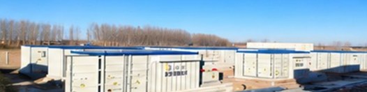

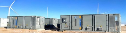
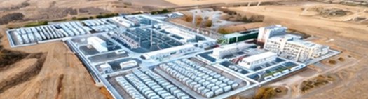
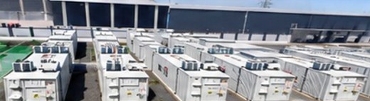
Partner track record — total deployed capacity across multiple countries. Safe, stable, ROI-optimised.
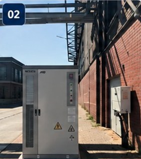
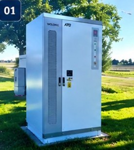
Active across four EU markets · outdoor IP-rated, built for durability · proven product maturity & safety.
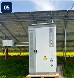
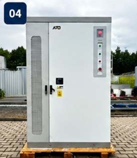
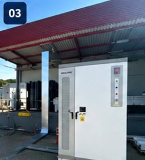
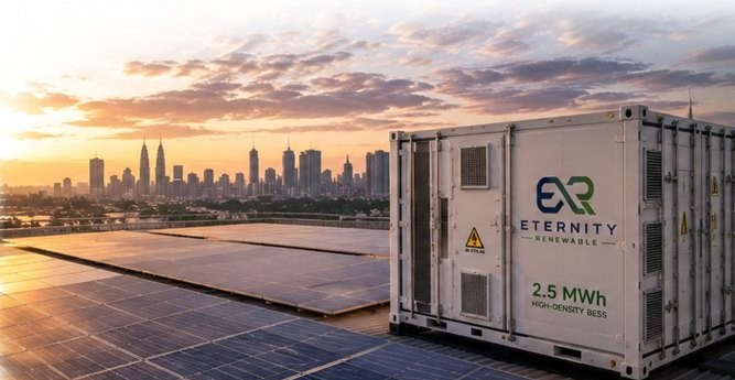
Eternity Renewable is ready to be your trusted energy partner — reliable, cost-effective and sustainable energy solutions for your business.